
eightbuttonMIDIfootswitch
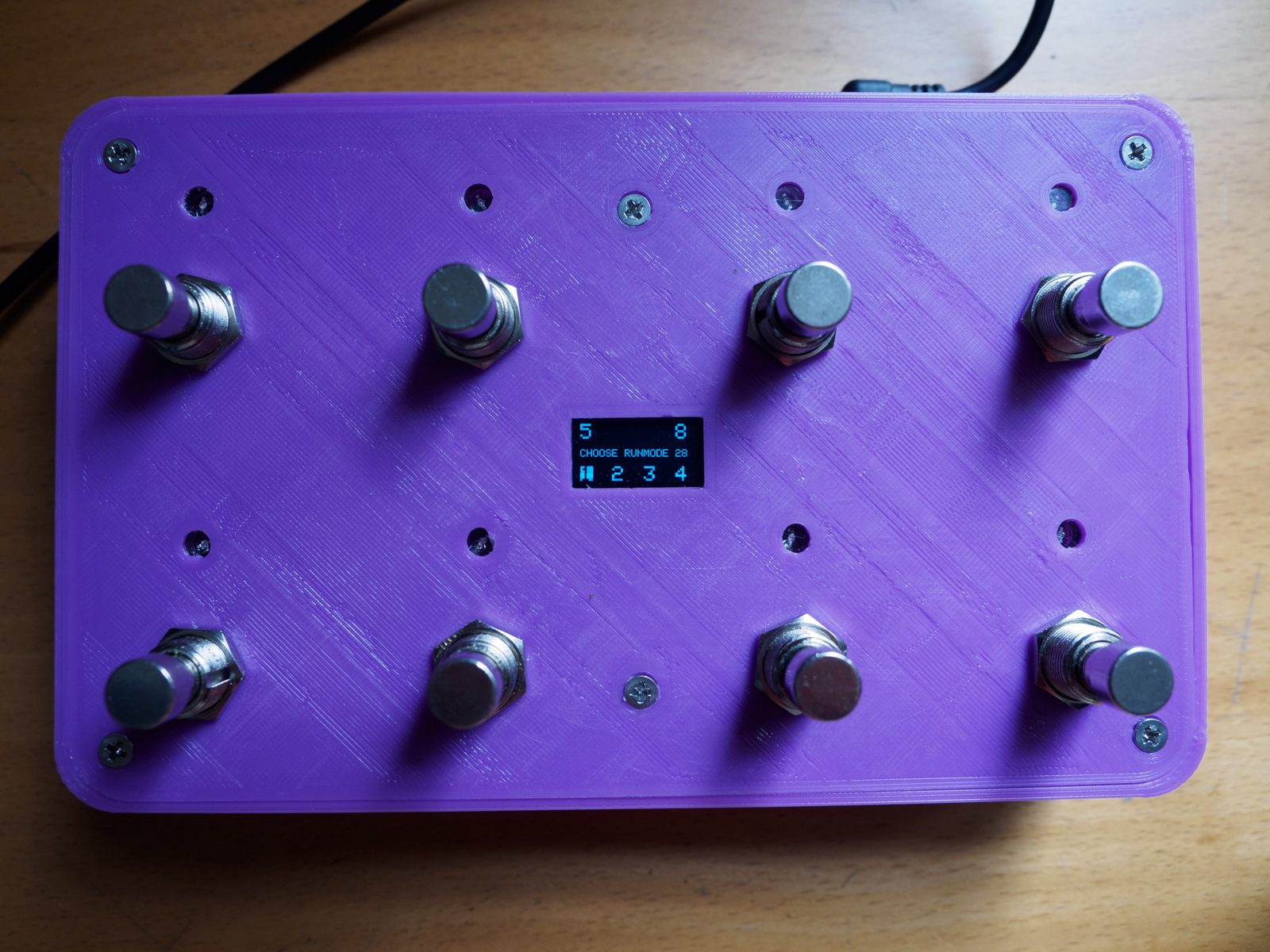
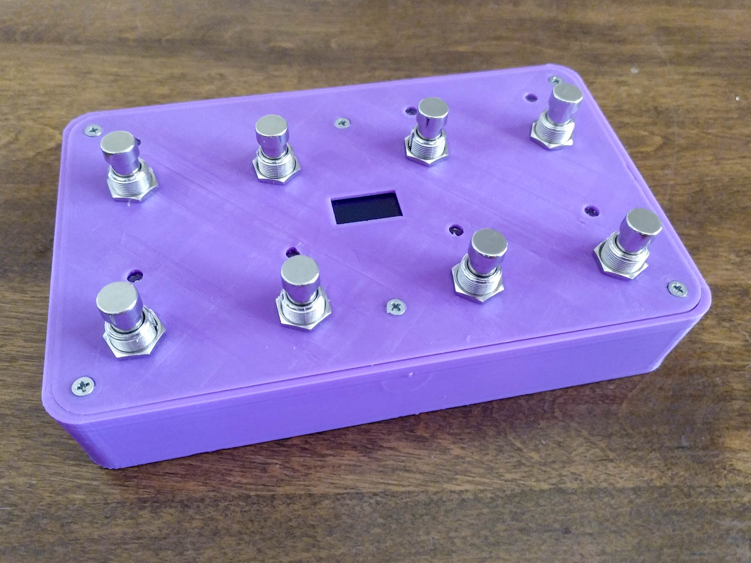
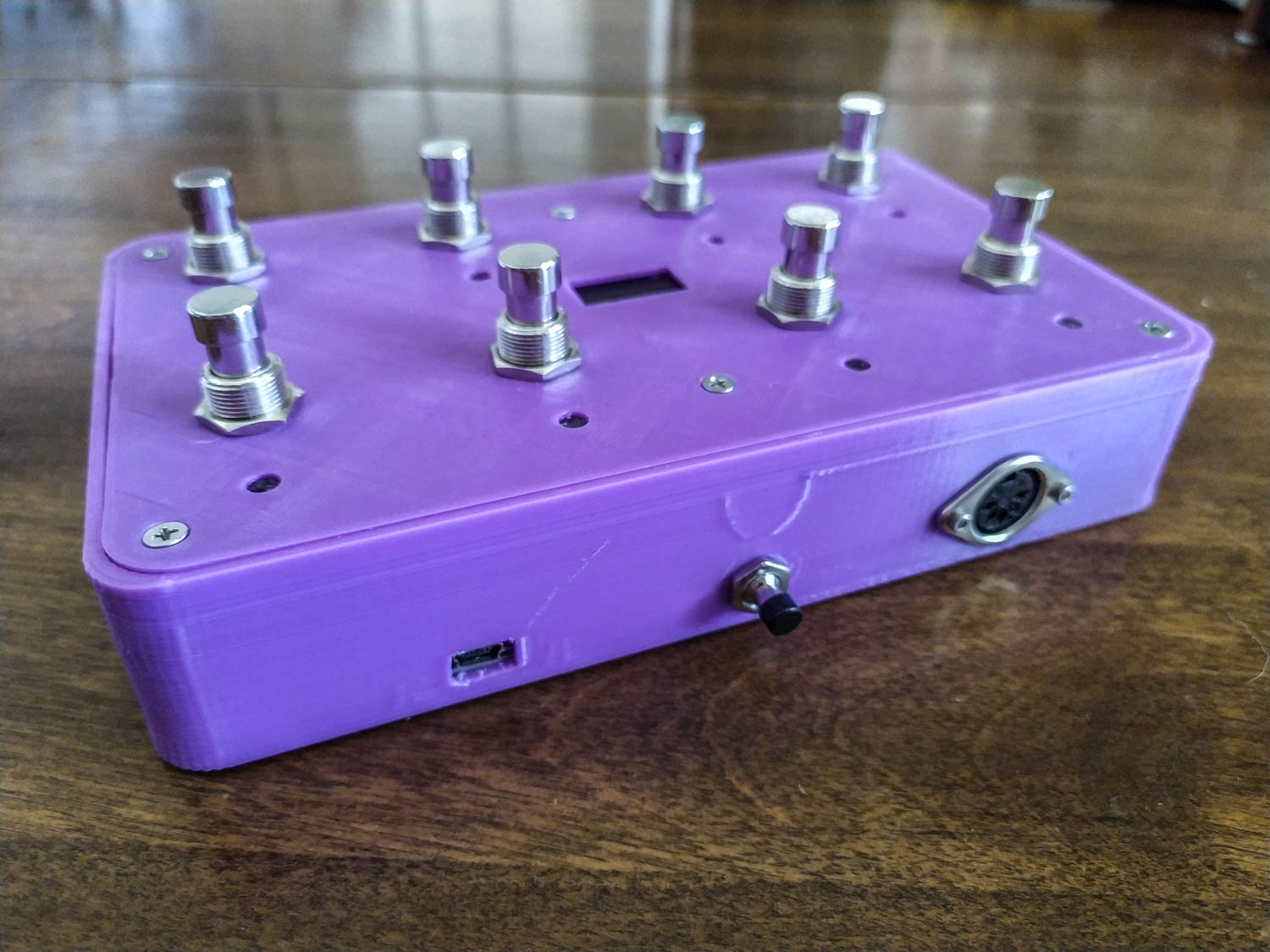
This is an 8 button MIDI footswitch I built, for my Synthstrom Deluge, as a way to manage the new looping functionality in the (now out) 3.0 firmware. I wanted to be able to turn the loop mode on/off, as well as other various functions, either via USB MIDI or via standard 5-pin MIDI.
This does that, and more! Check it out on Thingiverse
You can use either toggle (latching) or momentary switches. There are two versions of the code depending on which switch you use.
Currently there are 6 modes of operation selectable at boot. The selection screen can be returned to at any time by resetting the unit or pressing buttons 4 + 8 (top and bottom on the right side) together simultaneously.
- MIDI Note Momentary/Timed (on note sent on button press, off note sent after button is released (or preset time if using toggle switches))
- MIDI Note Toggle (press button once to turn on, press again to turn off)
- MIDI CC Momentary/Timed (same as mode 1 but with CC messages)
- MIDI CC Toggle (same as mode 2 but with CC)
- Program Change (pressing each of the 8 buttons sends a different Program Change message)
- Settings Menu (change channels, MIDI messages, default options)
If you do not choose an option the footswitch will start the default (mode 1) after a set timeout (6 seconds).
You can customize all of the messages sent by the footswitch. Currently the following options are configurable from the settings menu:
- CHAN - channel for NOTE/CC/PC messages (set separately)
- NOTE - MIDI note numbers and velocities
- CC - Control Change numbers and on/off values
- PC - Program Change numbers
- DEF - default runmode (RUNM), menu timeout (MENU), how long before OFF note/CC is sent (NOFF/COFF) (only in toggle version)
- LOAD - load values from EEPROM
- SAVE - save values to EEPROM (changes you make to settings will not be stored unless you press this)
The menu should be straight forward to use. There are a couple of screens that have no back button (due to all eight buttons being used for something else), they will time out to the previous screen after a set limit (which can be edited in the DEFaults menu).
Items used in this build:
- 3D Printer
- Soldering iron + solder
- Hookup wire (I used 28AWG) + appropriate heatshrink
- Tape (for binding wires, holding the OLED screen in place)
- Screwdriver
- Teensy ++2.0 (https://www.pjrc.com/store/teensypp.html)
- 8 x Guitar Footswitch, either momentary (https://www.aliexpress.com/item/32800932179.html) or latching (https://www.aliexpress.com/item/32826054526.html)
- 0.96" OLED I2C display (https://www.aliexpress.com/item/32896971385.html)
- 8 x 5mm 5V LEDs (https://www.aliexpress.com/item/32240559912.html)
- 5 pin MIDI port (https://www.aliexpress.com/item/32972269819.html)
- 2 x 220 ohm resistors for the MIDI port (see https://www.pjrc.com/teensy/td_libs_MIDI.html for wiring info)
- 7mm momentary push button (https://www.aliexpress.com/item/32790920961.html) as an easy way to update the Teensy without opening the case. Eventually I will replace this with a DC input jack.
- 6 x M3 countersunk screws, anything between 5 and 10mm in length will probably work (this is to hold the top of the housing down)
- 2 x M2 or M2.5 bolts and nuts, around 10mm length (to hold the MIDI port in place)
Rough pinout/wiring diagram:
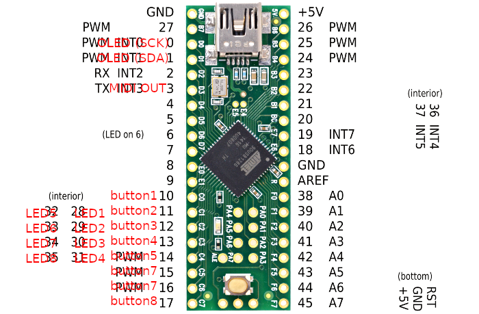
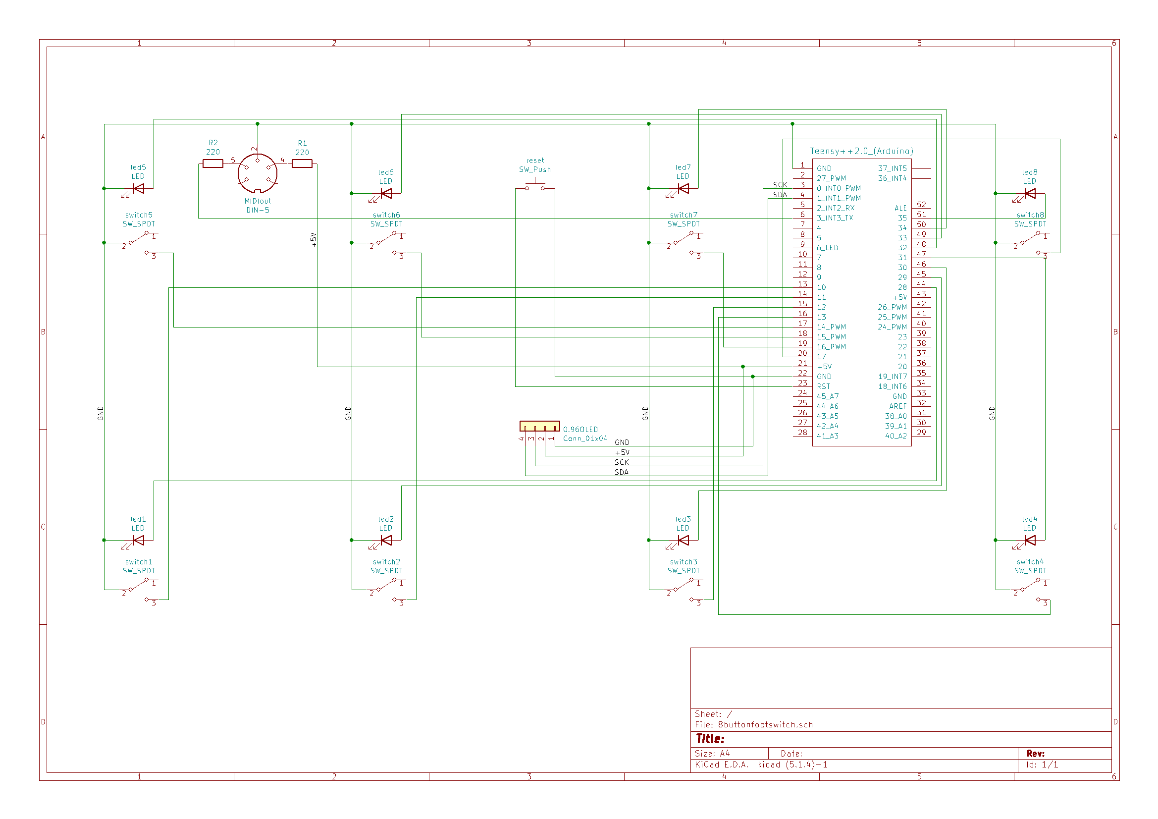
I have exported a schematic from KiCad that goes into more detail:
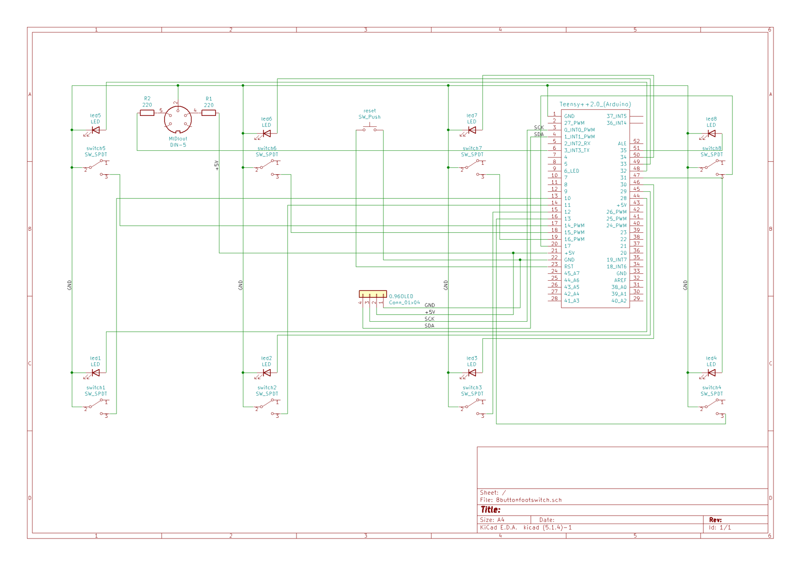 I’ve uploaded a video briefly showing how this works: https://www.youtube.com/watch?v=9XS2CDV4Rg0
Assembly instructions:
You can check out some pictures of my wiring here, here, and here.
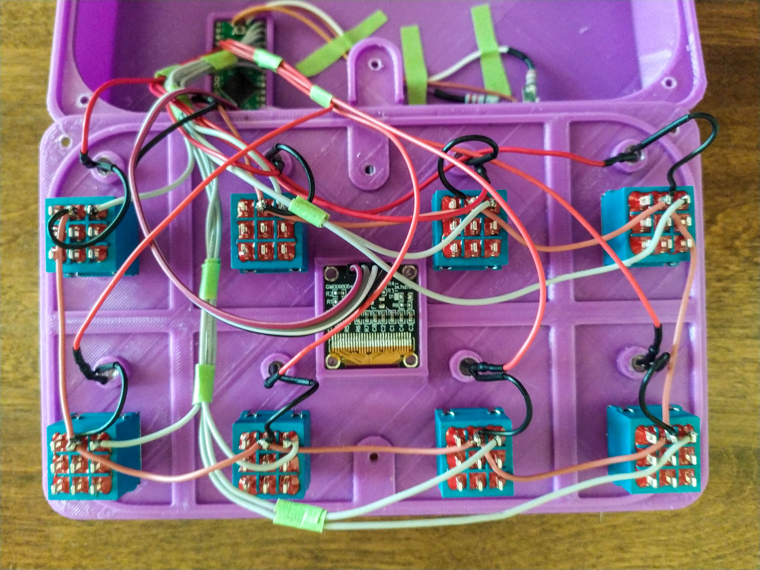
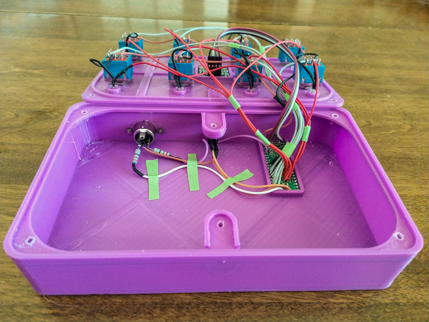
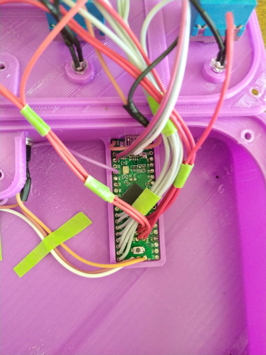
- Print the top and bottom of the housing with your handy 3D printer (I use a Tevo Tarantula myself). I printed in PLA with a layer height of 0.3mm. You will need to use supports for the bottom of the housing.
- Install the OLED screen in the top housing. I initially planned to screw it into place but ended up using double sided tape for now. Screws would be a better idea but I haven’t gone digging in my parts bin for something small enough yet.
- Wire the OLED screen to the Teensy, 5V and GND from wherever works for you and pin 0 for SCK/pin 1 for SDA.
- Install the footswitches in the top housing. Marvel at how footswitches are really hard to press with your fingers.
- Wire the footswitches to the Teensy. I wired the grounds first by daisy-chaining each switch to the next (and then the last switch the GND on the Teensy) and then wired the other sides of the switches to pins 10 through 17.
- Install the LEDs in the top housing. I made the holes in the top plate just large enough to jam the LEDs in so they don’t need any glue. Maybe a little glue around the base wouldn’t hurt.
- Wire the LEDs to the Teensy. I used pins 28 through 35 for the positive sides and then grounded each LED to the nearest switch. This is probably bad practice in electrical design but gosh darn if it doesn’t make for some easier wiring.
- Install the 7mm momentary switch in the appropriate hole in the bottom of the case (you figure it out). This is handy for updating the firmware on the Teensy and I may use it as a way to change between footswitch functions in the future.
- Wire the 7mm momentary switch to the RST and GND pins on the end of the Teensy furthest from the USB port (the bottom, in the pinout diagram).
- Solder 220 ohm resistors to pins 5 and 4 on the DIN-5 MIDI plug and install it into the bottom of the housing. See the MIDI library page here for more information/diagrams.
- Wire the MIDI plug as shown in the schematic. Pin 2 goes to GND (I ran it to the reset switch as it was close by), pin 5 (via 220 ohm resistor) goes to pin 3 on the Teensy, and pin 4 on the DIN-5 MIDI plug (via 220 ohm resistor) goes to a 5V pin on the Teensy (I used the one by the RST pin).
- Flash the appropriate code based on whether you used momentary or toggle/latching switches. If you used different pins than I did you will need to change the assignments in the code accordingly. Make sure you set the USB Type (under Tools->USB Type) to MIDI.
- Test it out! The LEDs will flash as you push the buttons and the screen will display the MIDI message number being sent.
- Squish the wires into place, close the housing and screw it together. You may need to bore out the screw holes a bit with a drill.
- Stomp those switches until your roommate/neighbour/family member complains about the noise.
Source code : 8buttonfootswitch-toggle.ino 8buttonfootswitch-momentary.ino
STL: 8buttonfootswitch-stl.zip
GitHub Repository
Dan